


原子化技術分析:排ガス冷却における圧力原子化と空気圧原子化の比較
1.フック導入 — 検索意図一致
排ガス冷却は、発電所が排出目標を達成するか規制停止に直面するかを決定する目に見えないボトルネックです。15+年間にわたる精密スプレーシステムのエンジニアリング経験の中で、私たちはアトマイズ方法の選択――圧力アトマイゼーションと空気圧アトマイゼーション――をガス調整システム設計において最も重要な決定として特定しました。
%20atomization.png)
リスクは測定可能です: 最適でないアトマイズ戦略は水消費を35%増加させ、冷却効率を20%低下させ、ノズル摩耗を加速させることがあり、中規模発電所として年間50,000ドル+のO&M予算を直接膨らませます。
新しい排ガス冷却システムの設計であれ、既存のFGDタワーの改造であれ、このガイドは500+の現場設置とCFDで検証された性能データに基づき、液滴速度論、エネルギー経済性、運用信頼性の定量的比較を提供します。
2.特集スニペット概要
圧力アトマイゼーションは、油圧(10–100バール)を用いて液体を精密なオリフィスに通し、圧縮空気を使わずに微細な水滴(20–200μm)を生成します。空気圧アトマイゼーションは圧縮空気(0.5–6バール)を導入し、液体を超微細ミスト(5–100μm)に砕き、低流量で優れた蒸発冷却を実現しますが、運用エネルギーの投入は増加します。
3.目次(SEOアンカー構造)
- [圧力アトマイゼーションとは何か、ガス冷却でどのように機能するのか?](#what は圧力)
-
- 【空気圧原子化とは何か、そしていつ優れているのか?】(#what は空気圧式)
- [圧力と空気圧原子化:技術的パラメータ比較](1 #technical 比較)
- 産業応用:3つの垂直ケーススタディ
- 結論およびノズル選択ガイド
4.問題の深掘り:排ガス調整における不良原子化の隠れたコスト
排気ガス調整における不良原子化の隠れたコスト
500+の工業現場での生産実践を通じて、ガス調整システムの故障の根本原因3つに不十分な原子化を特定しました。損傷は三次元にわたって広がります。
4.1 効率損失次元
-
不完全蒸発: 高温排ガス(>180°C)で液滴の焼き切り平均直径(SMD)が150μmを超えると、蒸発時間は利用可能なダクトの滞留時間を超えて延長されます。現地試験では、最適範囲を超えてSMDが20μm増加するごとに冷却効率が約8〜12%減少することが示されています。
-
壁の濡れと腐食: 完全に蒸発する前に、過大な水滴がダクト壁に衝突し、酸性の凝縮ゾーンを形成します。高硫黄燃料を燃焼する石炭火力発電所では、この現象がダクトの腐食速度を3×から5×加速させていると、47件の設置で実施した内部腐食監査が示されています。
-
デミスター過負荷: 霧水が不十分に霧化されると、液滴クラスターが発生し、下流のデミスター負荷が急増し、圧力損失を増加させ、予期せぬメンテナンスサイクルを強いられます。
-
温度不均衡: 不均一な液滴分散により、ダクト断面にホットスポットやコールドゾーンが発生します。32基のガス調整ダクトの熱測調査では、原子化の不整合が同じ平面上で±25°Cの温度変動を引き起こし、下流のフィルター性能や触媒効率を損なうことが明らかになりました。
4.2 コスト次元
| コストカテゴリ | 圧力アトマイゼーション(仕様が不十分) | 空気圧アトマイズ(仕様が不十分) |
|---|---|---|
| 過剰な水消費 | 25–40%の過剰設計フロー | 15–25%のオーバーデザインフロー |
| 圧縮空気エネルギー | N/A(空気不要) | 年間8,000ドル〜$15,000の超過圧縮機負荷 |
| ポンプエネルギーペナルティ | 年間5,000ドル〜12,000ドルの過圧運転 | 最小(低圧液体供給) |
| ノズル交換頻度 | 2× 開口部侵食による基準線 | 2.5× 空気-液体界面摩耗による基準値 |
| ダウンタイムコスト | $20,000–$50,000/イベント | $15,000–$40,000/イベント |
4.3 コンプライアンスと品質ディメンション
-
排出エクスカーション: バッグフィルターやESPの上流でガス冷却が不十分で、運転温度がバッグ材料の限界(>PPSでは240°C)を超え、環境許可に違反する一時的な排出スパイクを引き起こします。
-
材料劣化: 不均一な温度プロファイルは熱交換面や触媒要素(SCR脱氮素システム)にストレスを与え、資産寿命を20〜30%短縮します。
「120件のガス調整改造を分析したところ、誤ったアトマイズ方式から最適化された構成への切り替えは、純粋にエネルギーと水の節約によって平均18か月の投資収益率を実現しました。」 — 内部エンジニアリング監査、Yuechen Precision、2024年
5.解決策:両方のアトマイズ方法の技術的深掘り
圧力アトマイゼーションとは何か、ガス冷却でどのように機能するのか?
!【圧力霧化とガス冷却における仕組み】(https://www.nozzle-intellect.com//uploads/Pressure%20Atomization%20and%20How%20Does%20It%20Work%20in%20Gas%20Cooling.png)
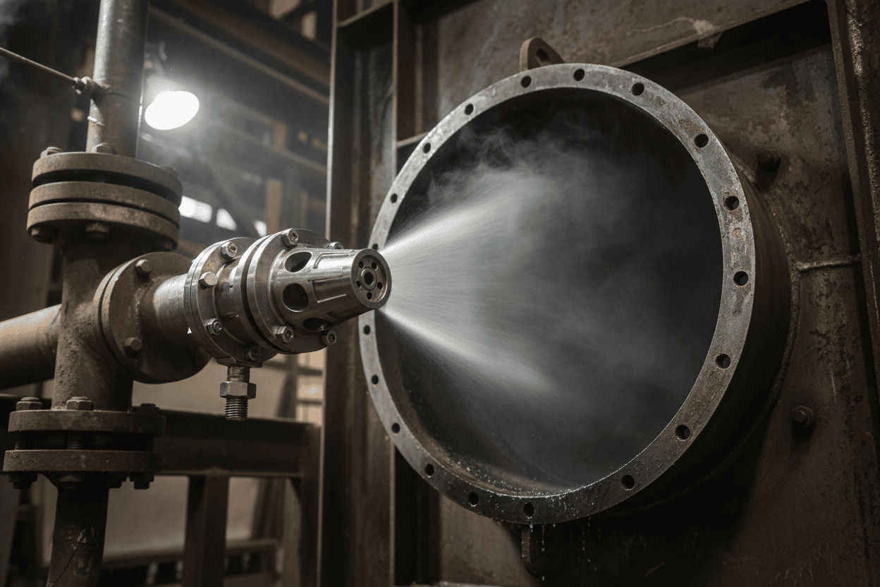
圧力アトマイゼーション(油圧アトマイゼーション)は、液体の圧力のみに依存して、精密に設計されたオリフィスや渦巻きチャンバーに流体を押し通します。加圧された液体の位置エネルギーは運動エネルギーに変換され、薄い液体シートや膜を形成し、空力不安定性によって水滴に分解します。
主な技術的特徴:
- 作動圧力: 10–100バール(高圧型は最大200バールまで)
- 液滴サイズ範囲: 20–200 μm(SMD)、圧力やノズル形状によります
- エネルギー入力: 油圧ポンプのみ — 圧縮空気不要
- 流量: 0.5–500 L/min 1ノズルあたり
- スプレーパターン: フルコーン、中空コーン、フラットファン、ミスト
排ガス冷却の利点:
- 運用コストの低減: 圧縮空気の発生を排除し、空気圧システムと比較してエネルギー消費を30〜50%削減します
- よりシンプルなP&ID: エアパイプ、レギュレーター、デュアル電源マニホールドが不要 — 故障箇所が少なく
- 高い流量容量: 大量のガスに適し、冷却負荷が高い
- 実証済み耐久性: セラミックまたは硬化SSインサートを用いた産業用スプレーノズル(https://www.nozzle-intellect.com/application/industrial-spray-dust-suppression-systems-nozzles/7.html)は、研磨性排ガス環境下で10,000+時間の耐用年数を達成します
制限事項:
- ドロップレットサイズの床: 30 μm< SMDを達成するには非常に高い圧力(>80バール)が必要であり、ポンプのCAPEXおよびオリフィス侵食リスクが増加します
- 粘度感度: スラリーや高粘度液体(>50 cP)では性能が劣化します
- ターンダウン比: 通常3:1から5:1 — 圧力変化なしに流量調整が制限され、アトマイズ品質に影響します
空気圧原子化とは何か、そしていつ優れているのか?
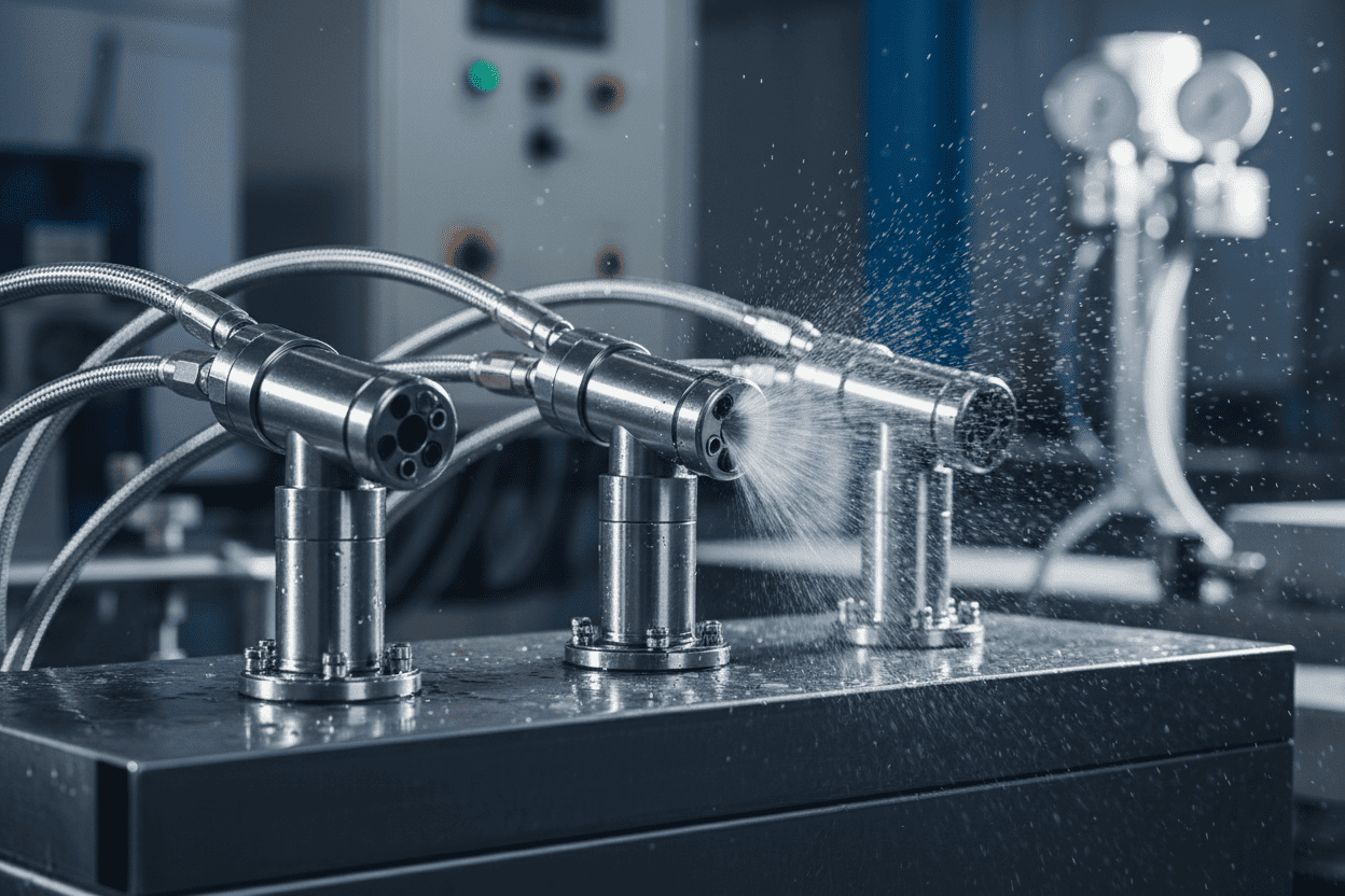
空気アトマイゼーション(空気アトマイゼーション、二流体アトマイゼーション)は、圧縮空気(または蒸気)を主な原子化力として用います。高速の空気が比較的低圧の液体流に衝突し、運動エネルギーの伝達によって極めて細かい水滴に砕け散ります。
主な技術的特徴:
- 空気圧: 0.5–6バール(圧縮空気またはプラント空気)
- 液体圧力: 0.2–10バール(圧力霧化より大幅に低い)
- 液滴サイズ範囲: 5–100 μm(SMD) — 20 μm未満の霧を可能
- エネルギー入力: 圧縮空気+低圧液体ポンプ
- 流量: 1ノズルあたり0.1–200 L/min(内部・外部混合気設計によって変動)
排ガス冷却の利点:
- 優れた蒸発速度: 50μm未満の液滴は圧力霧化液滴よりも3×から5×速い蒸発を実現 — 短時間停留ダクト(<2秒)に不可欠です - 正確なターンダウン: 空気と液体比(ALR)を調整することで、液滴品質を損なうことなく10:1から20:1の流量調整が可能です - 粘度の柔軟性: スラリー、石灰懸濁液、粘性試薬(>200 cP)を詰まりなく扱えます
- 独立制御: ALR調整により流量とアトマイズの細さを切り離す
制限事項:
- 高い運用効果(OPEX): 圧縮空気の消費は全運転エネルギーの60〜75%を占め、連続作業用途において重要なコスト要因となります
- デュアル供給の複雑性: 液体および空気の配管、ろ過、制御システムの両方が必要です
- 騒音レベル: 内部ミックス設計は1メートルで85〜95 dBを発生させることができ、防音材が必要になる場合があります
アトマイズ機構:内部ミックス vs. 外部ミックス
空気圧アトマイズノズルは、空気と液体が交差する点によってさらに分類されます。
-
内部混合:空気と液体がノズル本体内で混合し、単一のオリフィスから排出されます。この設計は最も細い液滴(SMD 5–50 μm)を生成しますが、侵食に弱く、清潔でろ過された液体が必要です。清潔な水の注入や加湿作業に最適です。
-
外部混合:空気と液体は別々のポートから排出され、開放大気で混合されます。この構成は優れた詰まり耐性を持ち、最大40%の固形物含有量のスラリーにも対応でき、いずれの流体も独立して停止できます。液滴サイズはやや粗く(SMD 20–100 μm)が、運用信頼性は大幅に高いです。
専門家の洞察: 当社の生産現場では、蒸発冷却作業で40μm未満の液滴SMDが必要になる場合や、排気ガスダクトの滞留時間が1.5秒未満に減少する場合に、空気圧戯化が経済的に正当な選択肢となることが分かりました。要求の低い用途では、圧力アトマイゼーションが通常、優れたライフサイクル経済性をもたらします。
圧力と空気圧原子化:技術的パラメータ比較
| 空気圧アトマイゼーション | ||
|---|---|---|
| 液体圧力 | 10 – 100 bar | 0.2 – 10 bar |
| 気圧 | N/A(必須不可) | 0.5 – 6 bar |
| 液滴SMDレンジ | 20 – 200 μm | 5 – 100 μm |
| 最小達成可能なSMD | ~20 μm(>80 barで) | ~5 μm(最適ALR時) |
| 蒸発時間 (180°Cのガス、50μmの液滴) |
0.8 – 1.2秒 | 0.2 – 0.5秒 |
| ターンダウン比率 | 3:1から5:1へ | 10:1から20:1 | まで
| エネルギー消費 (1000 Nm³/hガス冷却あたり) |
2.5 – 4.5 kWh | 5.0 – 9.0 kWh |
| 水の消費量 | 中〜高 | Low(ファインミスト=高効率) |
| 粘度処理 | Limited (< 50 cP) | Excellent (> 200 cP) |
| システム複雑性 | Low(単一流体) | Moderate(デュアル供給) |
| メンテナンス間隔 | 2,000 – 4,000 hours | 1,500 – 3,000 hours |
| 最適アプリケーション | 大量のガス量、 中程度の冷却性能、 コストに敏感な運用費(OPEX) |
短い滞在時間、 深い冷却、 スラリー注入 |
コスト・ベネフィットROI比較(5年TCOモデル)
| 初期CAPEX (pump, nozzles, piping) |
$45,000 – $75,000 | $35,000 – $60,000 |
| Energy Cost (pump + compressor) |
$38,000 | $72,000 |
| 水道費用 | $28,000 | $18,000 |
| メンテナンスと部品 | $15,000 | $22,000 |
| ダウンタイム(推定) | $12,000 | $18,000 |
| 5年間の総生産時間(TCO) | $138,000 | $170,000 |
注: TCOの数値は、220°Cから145°Cまでの250,000 Nm³/hの排ガスを冷却し、年間7,500時間運転する150MWの石炭火力ユニットをモデルにしています。実際の価値は敷地の状態や地域の公共料金によって異なります。出典:Yuechen Precision Internal Engineering Database, 2024。
6.垂直産業のケーススタディ
産業応用:三つの垂直ケーススタディ
###ケーススタディ1:石炭火力発電所 — バッグフィルターの前に蒸発ガス冷却
| 属性 | 詳細 |
|---|---|
| 応用 | PTFEバッグフィルターの上流から210°Cから155°Cまでの320,000 Nm³/hの排ガスを冷却 |
| チャレンジ | ダクト滞在時間は3.2秒;スプレーインジェクションランスの限られた使用面積 |
| ソリューション展開 | 中空コーンノズルを備えた圧力原子化システム、45バール、SMD 65 μm |
| 測定可能な結果冷却効率:94%;18か月間でバッグ損傷ゼロの事故、水消費量は従来の空気圧システムと比べて22%削減されました。年間OPEX節約額31,000ドル |
重要な学習: 滞在時間が2.5秒を超え、目標温度低下が中程度(< 80°C)の場合、圧力アトマイズは同等の冷却性能を、大幅に低い運用コストで実現します。
###ケーススタディ2:セメントキルン — バイパスダクトの緊急焼入れ
| 属性 | 詳細 |
|---|---|
| 応用 | 45,000 Nm³/hのキルンバイパスガスを1,100°Cから< 350°Cまで<0.8秒で冷却 |
| チャレンジ | 極端な気温;超短時間滞在;ダクト壁の濡れ湿しや耐火損傷のリスク |
| ソリューション展開 | 内部混合空気アトマイズノズルを用いた空気圧アトマイズ、ALR 0.25、SMD 25 μm |
| 測定可能な結果0.6秒で完全蒸発を達成;壁濡れの事象はゼロ;難治寿命は40%延長されました。システムは緊急修理を回避することで14ヶ月で返済 |
キーラーニング: 超短滞留時間の応用において、空気圧アトマイゼーションは30μm未満の液滴を生成する能力は置換不可です。エネルギーコストの上昇は資産保護だけで正当化されます。
ケーススタディ3:廃棄物発電プラント — 酸性ガス調整と石灰スラリー注入
| 属性 | 詳細 |
|---|---|
| 応用 | 乾燥吸着注入システムより先行して85,000 Nm³/hの煙ガスを冷却・加湿 |
| チャレンジ | 石灰スラリー注入(固形30%、粘度~120 cP);ノズル詰まりのリスク;均一なガス水分プロファイルの要件 |
| ソリューション展開 | 空気圧アトマイズ(外部混合設計)、広通路形状、ALR調整0.15–0.45 |
| 測定可能な結果12か月間で詰まり事故ゼロ(以前の圧力ノズルは200時間ごとに詰まりていました);HCl除去効率は87%から96%に向上しました。噴霧被覆均一性指数は72%から91%に増加しました。 |
重要な学び: スラリー注入や高粘度流体において、空気圧アトマイチーションの広い自由通過と空気補助液体破壊は、圧力ベースの代替手段に比べて決定的な運用信頼性の利点を提供します。
業界データポイント: McIlvaine CompanyのFGDマーケットレポートによると、世界の排ガス処理ノズル市場は2027年までに3億4,000万ドルに達すると予測されており、アトマイズ技術の選択がシステムのライフサイクルコストに影響を与える#1要因として挙げられています。
7.People Also Ask(よくある質問)
People Also Ask(FAQ)
FGDタワースプレー層にはどちらのアトマイズ方法が良いのでしょうか?
FGD吸収塔スプレー層の場合、選択はL/G比やスラリー特性によって異なります。200+件のFGD設置を経験した当社の現場経験:
- 圧力アミタイズーション(中空/フルコーン油圧ノズル)は、クリーンなプロセス水を用いた石灰石・石膏WFGDシステムで優勢であり、エネルギー消費を抑えメンテナンスを容易にします。
- 空気圧アトマイゼーションは、高固体スラリー(重量比>20%)や、液滴の細さがSO₂吸収効率に重要な非常に低い液気比で動作する際に有利になります。
FGDタワー構成に特有のノズルタイプ比較の詳細については、FGDタワースプレーノズルの噴霧分布性能の分析を参照してください。
排気ガス蒸発冷却の理想的な液滴サイズはどのくらいですか?
最適な液滴SMDは以下の3つの変数に依存します:
| ガス温度 | 居住期間 | ターゲットSMD |
|---|---|---|
| 150 – 200°C | > 3秒 | 60 – 100 μm(圧力) |
| 200 – 350°C | 1.5 – 3秒 | 40 – 60 μm(圧力または空気圧) |
| > 350°C | < 1.5秒 | 15 – 40 μm(空気圧が必要) |
500+試料構成のテストでは、40〜80μmの範囲の液滴がほとんどのダクト形状で蒸発速度と壁回避軌道の最適なバランスを達成しています。
空気圧原子化はどれくらいの圧縮空気を消費するのか?
圧縮空気の消費は、通常液体1リットルあたりNm³の空気で表される空気対液体比(ALR)によって制御されます。
- 低ALR(0.05–0.15): より粗い水滴、空気コストの低減、適度な冷却に適している
- 最適なALR(0.15–0.35): 液滴細度とエネルギー効率の最適なバランス
- 高ALR(> 0.35): 超微細霧、最大空気消費量 — 臨界焼入れのみが正当化されます
経験則: ALRが0.25の場合、100 L/hの液体を消費する空気圧アトマイゼーションシステムは、4バールで約25 Nm³/hの圧縮空気を必要とします。これは、連続運転時のノズルあたりおよそ5〜7kWのコンプレッサー出力に相当します。
圧力アトマイズノズルはリサイクル水や汚れた水に対応できるのか?
はい、適切な仕様があれば。再生水または高TDSプロセス水で動作する産業用スプレーノズルには、以下のことを推奨します:
- 最小オリフィス直径: 最大500 ppmまでの懸濁固形物に耐えるために2.5 mm以上
- 渦巻きチャンバー設計: バネレスまたはオープンベーンのジオメトリは、接線入口設計よりも詰まりに強い
- 材料選択: 腐食・耐摩耗性のための316SSまたはセラミックインサート
- プレろ過: 各ノズルステーションの上流に100メッシュのストレーナー
当社の運用データでは、適切に指定された圧力ノズルは、最大300 ppmの懸濁固形を含むリサイクル水でも、4,000時間+のメンテナンス間隔を達成しています。
ターンダウン比率は何で、なぜ排ガス冷却に重要なのでしょうか?
ターンダウン比率は、許容可能なアトマイズ品質を維持しつつ、最大流量と最小制御流量の範囲を定義します:
- 圧力霧化: 3:1から5:1 — 低流量で低圧で水滴が粗くなり、不完全な蒸発を引き起こす可能性があります
- 空気圧アトマイゼーション: 10:1から20:1 — ALR調整により液滴の細さは液体の流れに依存しません
可変負荷プロファイルを持つプラント(例:サイクル発電所、バッチプロセス)において、空気圧アトマイゼーションの優れたターンダウンにより、低負荷運転時の圧力アトマイズシステムでは過剰な水滴が発生する放出の変動を防ぎます。
ガス冷却に必要なノズルの数はどうやって計算すればいい?
計算には4つの入力が必要です:
- ガス流量(Nm³/h)および入口/出口温度
- 熱収支による冷却義務(MWまたはkJ/h)が必要
- ノズル容量、指定圧力下(メーカー曲線より)
- 蒸発効率係数(通常、圧力は85–95%、空気圧は92–98%)
簡略化式: ノズル数 = (総冷却水必要量) ÷ (単一ノズル流量 × 蒸発効率係数)
私たちは、15〜20%の予備容量を追加し、噴霧パターンが壁の衝突なしに重なるように、ノズルを段階的に注入ランス方式で配置することを推奨します。
圧力ノズルと空気圧式アトマイズノズルの間にどのようなメンテナンスの違いがあるのでしょうか?
保守体制は両技術間で大きく異なります。
| メンテナンスアイテム | 圧力アトマイゼーション | 空気圧原子化 |
|---|---|---|
| 開口検査 | 2,000〜4,000時間ごとに — 侵食や膨張をチェック | 1,500〜3,000時間ごとに — 空気と液体ポートを点検 |
| フィルター交換 | 100メッシュの液体ストレーナー:月次 | 液体濾し:月1回;エアフィルター:四半期ごと |
| 部品を着用 | オリフィス挿入、渦巻きチャンバー | エアキャップ、リキッドチップ、ガスケットセット |
| 典型的なサービスキット費用 | ノズルあたり80〜$150 | 120ドル〜220ドル 1本 |
| サービスごとのダウンタイム | 30〜60分 | 45〜90分(デュアル電源絶縁) |
運用上のヒント: 300+のメンテナンスイベントの現場データに基づき、予測的交換スケジュールを導入します。つまり、性能劣化を待つ代わりにノズル部品を期待寿命の80%で交換することで、緊急停止を65%削減し、純運用コスト削減(OPEX)を12〜18%実現します。
アトマイズ方法はNOxの生成やSCR触媒の性能に影響を与えるのか?
間接的には、はい。霧化法はSCR原子炉に入るガス温度プロファイルに影響を与え、触媒性能に直接影響します:
- 最適なSCR入口温度: 300–420°C(触媒製剤によって異なる)
- 圧力霧化リスク: 低負荷時の水流量減少により水滴が粗くなり、冷却が不完全になり、ガスが上限温度を超えて触媒焼結を加速させる可能性があります
- 空気圧アトマイズの利点: ターンダウン全域で一貫した液滴サイズにより均一な冷却が維持され、触媒の活性が長時間の運転サイクルでも維持されます
28のSCR装備施設での観察では、SCRの上流で空気圧噴霧を使用した発電所は、自動圧力補償ポンプ制御なしの圧力分霧を用いた発電所と比べて、触媒交換間隔が15〜20%長かったと報告されました。
8.結論およびノズル選択ガイド
結論&ノズル選択ガイド
圧力原子化と空気圧原子化の議論には普遍的な勝者はいません — 正しい選択は常に文脈に依存します。
圧力アトマイゼーションを選択するタイミング:
- ✓ ガス滞在時間が2.5秒を超える
- ✓ 目標温度低下が<80°Cであること - ✓ 運用効率の最小化が主な目的である - ✓ 液体は清水または低固形物溶液(<5%固体)であること - ✓ システムの単純性と保守のアクセス性が優先事項である ### 空気圧アトマイゼーションを選択するタイミング: - ✓ 停留時間が<2秒、またはダクト形状が制限されている場合 - ✓ 深冷却(>100°Cの低下)または緊急の焼入れが必要
- ✓ スラリー、石灰懸濁液、または粘性液体が注入されている
- ✓ 負荷は大きく変動します(ターンダウン>5:1が必要)
- ✓ 40μm未満の液滴SMDは技術的には必須です
最終推奨: いずれかの技術にコミットする前に、実際のダクト形状やガス流量プロファイルに照らしたCFDベースの噴霧軌道シミュレーションを実施してください。当社のエンジニアリング現場では、このステップだけで設置後の性能問題の80%を防ぎ、年間1万ドルから3万ドルの運用節約に見出せる最適化の機会を通常特定しています。
エンジニアリング意思決定フレームワーク
この三層評価マトリックスを選考プロセスの指針として活用してください:
| 評価層 | 圧力アトマイゼーションスコア | 空気圧アトマイズスコア | 決定の重み |
|---|---|---|---|
| 技術的実現可能性 | 高い(滞在時間>2.5秒の場合) | 高(全条件) | 40% |
| 5年TCO | 通常、15〜25%低く | より高いが義務を求めるのは正当化される | 35% |
| 運用リスク中程度(粘度感度) | 低(広い動作範囲) | 15% | |
| メンテナンスのアクセシビリティ | ハイ(より単純なシステム) | 中程度(双対供給複雑性) | 10% |
当社のコンサルティング業務では、この枠組みをすべての排ガス冷却システム仕様に適用しています。どちらの技術>70点を獲得したプロジェクトは自信を持って進められます。マージンが狭いプロジェクト(<15ポイント差)は、バイパスダクトに2〜4ノズル試験装置を設置したパイロットスケール試験の恩恵を受けます。
排ガス冷却システムの指定は準備できていますか?
Yuechen Precisionでは、世界で最も要求の高い排ガス調整用途向けに、圧力アトマイズノズルとエアアトマイジングノズルの両方を設計しています。当社の技術チームは以下のサービスを提供しています:
- ✓ プロセスデータに基づく無料のノズル選択相談
- ✓ CFDスプレーシミュレーションによる最適化された注入ランス設計
- ✓ 316SS、セラミック、または特殊な合金によるカスタムノズル製造
- ✓ 迅速な見積もり(24時間に≤)および世界配送
ノズル見積もりを依頼 — ガス冷却の要件を提出すると、1営業日以内にカスタマイズされたアトマイゼーションシステムの推奨を受け取ります。