


石灰岩スラリーノズル詰まり対策:大きなフリーパス幾何学設計の習得
石炭火力発電所の排ガス脱硫(FGD)エンジニアにとって、KPIを最も早く台無しにする指標が一つあります。それが「予期せぬダウンタイム」です。石灰岩スラリーノズルが詰まると、スクラビングプロセス全体が劣化し、SO2の排出急増や壊滅的な運転停止を引き起こします。根本原因はポンプや圧力であることは稀です。これは根本的にノズル内部の幾何学的欠陥です。この包括的なホワイトペーパースタイルガイドでは、スラリー詰まりの流体力学を解説し、従来の内部ベーンがなぜ故障するのかを説明し、最大自由通過(MFP)幾何学的設計を採用することでこれらの高価なボトルネックを永久に解消できることを示します。
目次
- 1.FGDクロッグの理解:幾何学的破壊のコスト
- [2.コアコンセプトの簡略化:なぜ内部ベーンが原因なのか)(#2-core-concepts-simplified-なぜ内部ベーンが犯人なのか)
- 3.ステップバイステップガイド:正しい幾何学デザインの選び方
- 4.専門家のヒントと避けるべき一般的な落とし穴
- 5.結論と最終思考
1.FGDの詰まりを理解する:幾何学的破壊のコスト
現代の化学流体制御やFGDシステムにおいて、石灰石スラリーは非常に扱いにくい媒体として知られています。固体の濃度は重量で10%から20%の範囲であることが多く、流体は水というよりも液体のサンドペーパーのように振る舞います。
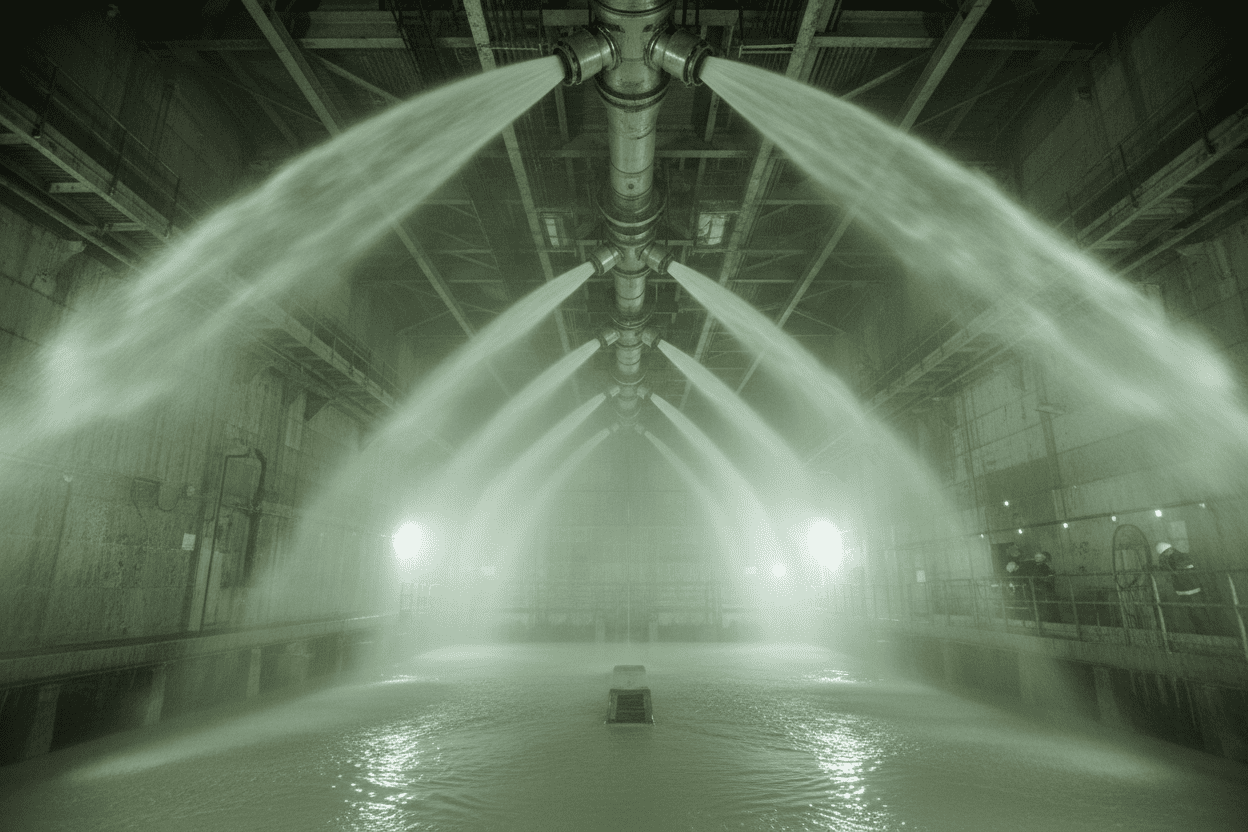
r/ChemicalEngineeringやEng-Tipsのようなフォーラムでエンジニアが日々の運用悪夢について話すとき、ノズルの詰まりは常に最優先事項です。単一の詰まったノズルは、スクラバータワーの吸収ゾーンに「ドライスポット」を形成します。これにより、未処理の排ガスはスクラビング工程を回避できます。これを補うために、オペレーターはポンプ圧力を上げることが多く、これによりシステム全体の摩耗や損傷が加速します。予期せぬ停止がタワー内に物理的に侵入し、石灰岩を削り取り、ノズルを交換する最終的なコストは、1時間あたり数万ドルにのぼることがあります。
これを解決するためには、化学添加剤や高価なろ過システムに注目するのをやめ、ノズル自体の内部形状*を再検討する必要があります。
2.コアコンセプトの簡略化:なぜ内部ベーンが原因なのか
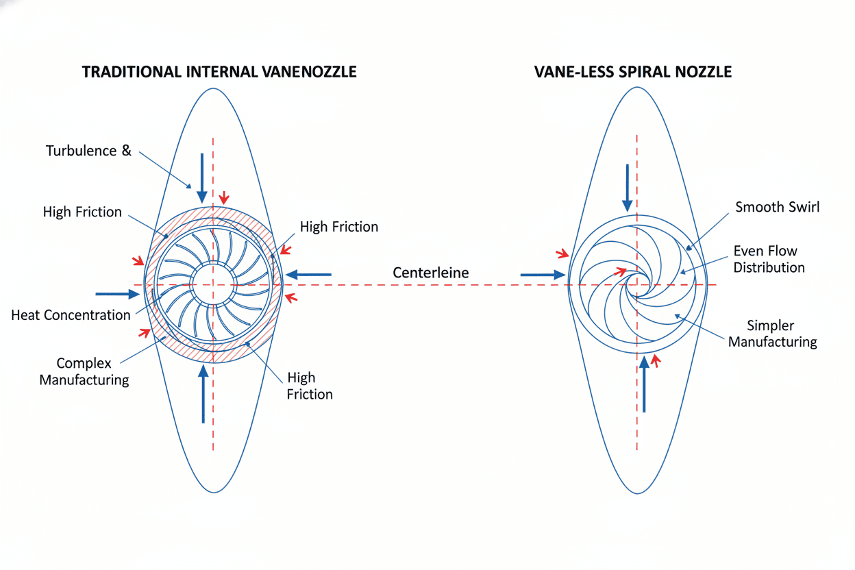
なぜノズルが詰まるのかを理解するには、従来のノズル工学を見直す必要があります。歴史的には、均一な噴霧パターンを作るために、ノズルは内部ベーン(渦巻きインサート)を使用していました。
「料金所」のアナロジー
車が水分子を表し、巨大な大型トラックが固体の石灰岩粒子を表す多車線高速道路を想像してみてください。内部ベーンは複雑で狭い料金所構造のようにこの高速道路の真ん中に配置されています。純水(車)は料金所を容易に通過できますが、重い石灰岩の粒子(トラック)は必ずバリアに衝突し、積み重なり、最終的に道路全体を塞いでしまいます。流体力学では、ここから石灰化と凝集が始まります。
最大自由通過(MFP)の定義
料金所に対する工学的対策は最大自由通過(MFP)です。簡単に言えば、MFPとはノズル内部の最も狭い部分を通過できる最大の剛性のある球体(ビー玉のようなもの)の直径を指します。
内部ベーンを外すと料金所も外されます。スラリーは広い高速道路を流れることもあります。高いMFPは、石灰岩粒子が固まっても閉じ込められるのではなく流出されます。
幾何学的設計比較表
| 特徴量 / 計量 | 伝統的なベーンノズル | 大きな自由通路(スパイラル/ベーンなし) |
|---|---|---|
| 内部構造 | 複雑な渦巻きインサート / Xベーン | オープンパイプ / 外部下降ヘリックス |
| 詰まりリスク | 極高(チョークポイントとして機能) | 極めて低い(制限のない流路) |
| MFPサイズ | 通常、開口径の30〜50% | *開口径の90〜100%まで |
| メンテナンス費用 | 高(頻繁な手動清掃が必要) | 低(自己クリアリング幾何学) |
| 最優秀アプリケーション | 清浄な水、低粘度流体 | FGD、高固形石灰岩スラリー、採掘 |
3.ステップバイステップガイド:適切な幾何学デザインの選び方
巨大なMFPを搭載したノズルを選ぶのは明白な選択のように思えますが、重要な工学的トレードオフが生じます。穴が大きすぎる場合、どうやって液体を霧化するのか?
大きな穴は詰まりを防ぎますが、通常は巨大で重い水滴を真下に落とし、SO2吸収に利用可能な表面積を大幅に減少させます。解決策は、スパイラルノズルで最も一般的に見られる外部インピンジメント形状*にあります。
ノズルの中から液体を渦巻く代わりに、螺旋ノズルは流体を大きく障害のないオリフィスから出て、螺旋状の外面に激しく衝突させます。これにより濃厚なスラリーが細かい滴の層に分断されます。FGDタワーの噴霧用ノズルでスパイラルノズルとソリッドコーンノズル(https://www.nozzle-intellect.com/blogDetail/spiral-vs-solid-cone-nozzle-fgd-tower-spray-distribution-guide/19.html)を比較すると、スパイラル設計は高固固体環境で一貫して優れています。なぜなら、霧化と内部制限を切り離すからです。
3.1 シナリオA:高固形石灰岩スラリー(FGD吸収材)のサイズ調整
吸収塔のノズルを指定する際は、推測に頼ることはできません。この厳格でデータ駆動型の選考プロセスに従ってください:
- 最大粒子サイズの決定: 石灰岩のミリングプロセスを分析してください。スラリーラインに入り込む可能性のある固体粒子(または凝集した塊)の絶対最大直径を求めます。
- 3倍ルールを適用する: ノズルのMFPは最大粒子サイズの少なくとも3倍以上でなければなりません。(例:最大粒子サイズが4mmの場合、MFPは≥12mmでなければなりません)。
- 流量と圧力の比較を確認: ポンプが新たに指定されたオリフィスサイズで必要な圧力を維持でき、望ましい噴霧角度を達成できるようにします。
工学仕様/選択データ表
| スラリー固形成分 | 最大粒子サイズ | 最低必要MFP | 推奨幾何学デザイン | 期待液滴サイズ(SMD) |
|---|---|---|---|---|
| < 5%(軽度スラリー) | 2 mm | > 6 mm | オープンパイプフルコーン | 1500 - 2000 μm |
| 10% - 15%(標準) | 5 mm | > 15mm | 大きな自由通路螺旋 | 2000 - 3000 μm |
| > 20%(重スラリー) | 8mm | > 24mm | 最大自由通過螺旋 / 接線 | 2500 - 4000 μm |
3.2 シナリオB:ガス消焼と粉塵抑制
FGDタワーが最も重要な分野ですが、発電所は石炭粉塵抑制や高温ガス焼光などの二次システムでも詰まりの問題に直面しています。幾何学的設計が産業用スプレーダスト抑制ノズルにどのように影響するかをより広く理解するには、同じMFPの原則が適用されます。
しかし、ガス冷却では、スクラビングよりも液滴のサイズがはるかに重要です。大型MFPの必要性と、湿った底面を防ぐための超細かい液滴のバランスに苦労しているなら、単一流体油圧ノズルを完全にやめる必要があるかもしれません。そのような場合、圧力と空気圧の原子化を詳しく調べると、圧縮空気を導入することで、小さな詰まりやすいオリフィスを必要とせずに液体を微小ミストに砕けることが明らかになります。
4.専門家のアドバイスと避けるべき一般的な落とし穴
数十年の現場経験と化学工学フォーラムの死後故障報告の分析を踏まえ、スラリーノズルを扱う際にエンジニアがよく犯す落とし穴は以下の通りです。
- 落とし穴1:「名目上のパイプサイズ」を実際のMFPより信頼すること。
- *間違い:内部通路が2インチだと仮定して「2インチノズル」を購入すること。
- 現実: 内部ベーン付きの2インチノズルは、MFPが0.5インチしかないこともあります。必ずメーカーに具体的なMFPサイズを要求してください。
- 落とし穴2:ポンプ劣化の無視。
- 失敗: ポンプの初日のパフォーマンスに基づいてノズルアレイを設計すること。
- 現実: 研磨性のある石灰岩はポンプのインペラーを急速に摩耗させます。ポンプヘッドが下がると、ノズルの圧力も下がります。圧力が低いほど霧化が悪くなります。ノズルの形状が詰まりを防ぐために高速に依存している場合、摩耗すると即座に詰まりが発生します。
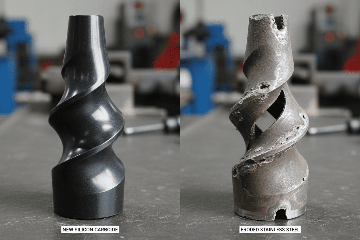
- 落とし穴3:間違った素材の使用。
- 間違い: 高速スパイラルノズルに316ステンレススチールを使用すること。
- 現実: 螺旋ノズルの外部らせんは、研磨剤のスラリーによって激しく打たれます。316SSは数か月で浸食され、噴霧パターンが破壊されます。FGDスラリー用途には必ず炭化シリコン(SiC)または特殊セラミックスを指定してください。
5.結論と最終的な感想
FGD石灰岩スラリーシステムでの詰まりは避けられない現象ではありません。これは幾何学的ノズルの選択が誤ったことの症状です。内部ベーンを排除し最大自由通過(MFP)を優先することで、エンジニアはチョークポイントでの凝集問題を根本的に解決できます。
核心ルールを忘れないでください:ノズルのMFPは最大のスラリー粒子の少なくとも3倍の大きさでなければなりません。 外部インピンジメントスパイラルノズルのような設計を活用することで、詰まりの防止と効率的なSO2スクラブに必要な霧化の微妙なバランスを保つことができます。
クイックサマリーテーブル
| 重要なポイント | 実践的なエンジニアリングアドバイス |
|---|---|
| 根本原因内部のベーンは「料金所」として機能し、固体の石灰岩粒子を捕捉します。 | |
| 解決策 | ベーンレス/大型フリーパッセージジオメトリ(例:スパイラルノズル)に切り替えてください。 |
| 黄金律 | MFP>スラリー中の最大固体粒子径の3倍です。 |
| 素材の選択 | スラリースパイラルには標準的なステンレス鋼は絶対に使わないでください。炭素化ケイ素(SiC)の義務化。 |
| 投資回数 | 予期せぬダウンタイムを排除することで、最初の停止を回避したアップグレードノズルの費用が支払われます。 |
FGDシステムの最適化は準備できていますか? 悪い幾何学設計にメンテナンススケジュールを決めさせるのはやめましょう。現在のP&IDを確認し、設置ノズルのMFP評価を確認し、流体力学の専門家に相談して、真の大型フリーパッセージソリューションでスクラバータワーを改造しましょう。